Item group
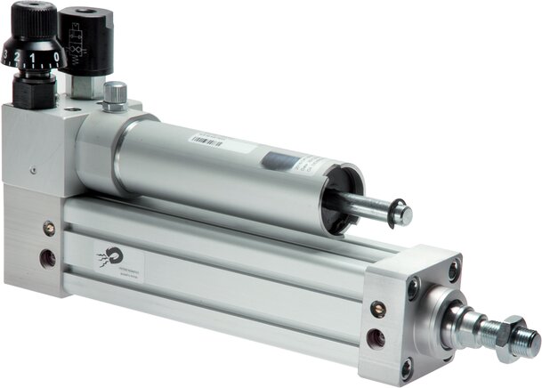
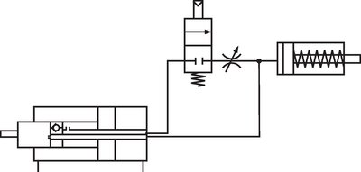
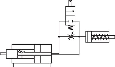
Oil brake cylinder, main mounting dimensions acc. to ISO 15552

Original parts from:
Re-coding service
In our online shop, you can also search by item numbers of other suppliers.
Payment options:
Cash on delivery
Invoice